Page 33 - PITTURE E VERNICI EUROPEAN COATINGS Issue 3/May-June 2017
P. 33
RAW MATERIALS
FILLERS CARICHE
MATERIE PRIME
Type of spheres
Tipo sfere
D50 (m)
% Vol of spheres
Vol % sfere
Thickness of dry paint
Spessore pittura asciutta
TSR
UV
Vis
NIR
SRI (mid-wind conditions)
SRI (condizione con vento medio
ext bmk
-
245
85,8%
6,8%
89,2%
86,4%
107,5
ext 00
S22
35
23,1%
250
87,4%
6,1%
90,0%
88,7%
109,8
ext 01
K25
55
24,3%
265
87,0%
6,4%
89,8%
88,2%
109,3
ext 02
K15
60
24,3%
220
86,3%
6,6%
89,3%
87,3%
108,3
ext 03
IM16K
22
24,3%
220
88,3%
6,2%
90,9%
89,6%
111,0
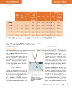
Tab. 3 TSR and SRI values of tested commercial paints and compared with paints formulated with 3M glass bubbles
Valori di TSR e SRI misurati sui campioni di pittura sperimentale contenenti microsfere di vetro 3M
by the addition of 3M Glass Bubbles. In addition we can note that the TSR value increases when we the size of the microspheres decreases.
RESULTS ANALYSIS
The heat reflective properties of a coating are regulated by a number of physical phenomena that help to
build a model which well simulates the real
system behavior.
When an electromagnetic wave meets a paint film, consisting of a certain number of pigment particles dispersed in a continuous medium, it undergoes multiple scattering. At each scattering the wave is deflected by a certain angle from its previous trajectory, as stated by Snell's law:
n1 sin θ1 = n2 sin θ2
where θ1 and θ2 are respectively the angles formed by the affecting ray and the refracted ray with the normal at the interface between the two media and, n1 and n2 the refractive indices of the two media (Fig. 2).
After a number of scatterings, the wave emerges from the film and it is spread in the same origin medium or in that opposite. The
di Snell:
n1 sin θ1 = n2 sin θ2
dove θ1 e θ2 sono rispettivamente gli angoli formati dal raggio incidente e dal raggio rifratto con la normale all’inter- faccia tra i due mezzi e, n1 ed n2 gli indici
Fig. 1
Light refraction at the interface between two medi awith different refractive index
Rifrazione della luce all’interfaccia tra due mezzi con indice di rifrazione diverso
di rifrazione dei due mezzi (Fig. 2).
Dopo un certo numero di scattering, l’onda riemerge dal film e viene diffusa nello stesso mezzo di provenienza o in quello opposto. Maggiore è la differenza tra gli indici di rifrazione dei due mezzi, maggiore sarà lo scattering dell’onda elettromagnetica e dunque la probabilità che questa riemerga nello stesso mezzo di provenienza.
Le più comuni pitture hanno matrici con indici di rifrazione compresi tra 1,45 e 1,60. Introdurre cariche a basso indice di rifra- zione può essere quindi una strategia per introdurre ulteriori eterogeneità nelle pitture e dunque nuove superfici scatteranti. Quando l’onda elettromagnetica, prove- niente da un mezzo a indice di rifrazione relativamente alto, raggiunge la microsfera piena d’aria che ha un indice di rifrazione più basso, viene deviata con angoli di rifrazione
Pitture e Vernici - European Coatings - Formulation 3 / 2017 29