
Page 41 - COMPOSITE SOLUTIONS - Fascicolo 2/2016 - Issue 2/2016
P. 41
weight of 21 kg. Here, nothing could be shaved off. So to achieve the desired weight reduction the first job was to replace the two previous motors with a single 5 kW electric motor. The suspension and steering system were also replaced; they are now made mainly from carbon. But the car was still too heavy and the only area left to save weight was the vehicle body itself.
THE BODY
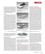
The self-supporting body made by the students is a 1.72 meter wide and 4.50 meter long monocoque construction comprising a top and a bottom shell made from CFRP (carbon-fiber- reinforced plastic). Using a vacuum infusion process, the students manufactured the shells from different prepregs; a 0.0 8mm Textreme, a UD fabric and a 0.23mm twill. The core material is Rohacell. Once cured and demolded, plastic shells of this size are strong as far as the material is concerned, but still very unstable due to their light weight, curved shape and large surface area. Therefore the top and the bottom shell needed a framework of stiffening ribs with an extra stiffening construction, the torsion box, for the bottom shell (Fig. 2 and 3), to prevent bending and twisting of the substructure. After assembly the two shells will give the solar car its final aerodynamic shape (Fig. 4 and 5).
partiti per l'Australia con il loro capolavoro Punch One. Tuttavia, prima che tutto questo potesse avve- rarsi, l’automobile ad energia solare doveva essere progettata e costruita dal nulla.
OGNI GRAMMO CONTA
Meno massa sta per minor consumo di energia, con un peso massimo totale di 165 kg. Punch One doveva essere infine più leggera di 10 kg rispetto al modello precedente e ben 25 kg più leggera della maggior parte dei modelli con- correnti. Sei metri quadrati della superficie del veicolo sono rivestiti da celle solari al silicio ul- trasottili. Eppure, nonostante il loro scarso peso, esse hanno ancora un peso totale di 8 kg. Il com- ponente più pesante dell’automobile è la batteria solare, con un peso massimo specificato di 21 kg. In questo caso non ci sono eccedenze da elimi- nare. Quindi, per ottenere la riduzione di peso desiderata, il primo obiettivo è stato sostituire i due motori precedenti con un motore elettrico di 5 kW. Anche sospensioni e ingranaggi sono
Photo: Punch Powertrain Solar Team
Fig 2 - Plasma-treated monocoque bottom shell showing ribs and torsion box
Guscio inferiore scocca trattato al plasma con inserti di rinforzo e box di torsione
Photo: Punch Powertrain Solar Team
Fig 3 - Plasma-treated structure of the stiffening ribs in the top shell
Struttura degli inserti di rinforzo sul guscio superiore trattata al plasma
Fig 4 - Assembly of the different car body layers
Assemblaggio dei vari strati della carrozzeria
Fig 5 - The finished solar car Punch One
Punch One finita, l’auto a energia solare
stati sostituiti e attualmente sono realizzati prin- cipalmente in carbonio. Ma l’automobile si pre- sentava ancora troppo pesante e l’unica area in cui risparmiare peso era la carrozzeria stessa.
LA CARROZZERIA
La carrozzeria autoportante realizzata dagli studenti è una struttura monoscocca larga 1,72 metri e lunga 4,50 metri, comprendente un gu- scio superiore e uno inferiore costruiti con CFRP (composito rinforzato al carbonio). Utilizzando il processo di infusione sottovuoto, gli studenti han- no prodotto i gusci con vari tipi di prepregs; 0,08 mm Textreme, tessuto UD e twill da 0,23 mm.
BONDING INSTEAD OF LAMINATION
The joining force between the rigid foam ribs encased in Textreme and the bodywork must be strong enough to produce a back pull and coun- teract any tensile or compressive stresses in the shells in any direction. In view of the challenges the car body has to face during races, previous student teams had always chosen to laminate these static elements. Multiple layers and lengths of prepreg strips were applied at each attachment point of the ribs. But this joining method was not only extremely labor-intensive and time-consum- ing; all the extra prepreg strips also increased the weight. So the question was whether it would be possible after all to achieve a high-strength bond using adhesives instead of a lamination process. Various adhesives manufactured by Henkel were tested to find an alternative. Due to the car’s strong vibrations, an adhesive was required which had both high elasticity and a short open time for fast bonding operations. Loctite EA 466 was ultimately chosen, a fast curing, 2-component epoxy resin adhesive. However, in the first tensile-shear-force tests failure occurred as a result of an adhesive fracture (Fig.6) instead of the expected cohesive fracture. At the fracture point there was no adhesive on the CFRP surface that was to be bonded, despite the fact that this had been pretreated with a special cleaner. “We
Il materiale d’anima è Rohacell. Una volta reti- colati e distaccati dallo stampo, i gusci di questa dimensione sono robusti grazie al materiale, ma ancora instabili a causa del loro scarso peso, della forma curva e dell’area superficiale ampia. Di conseguenza, i due gusci richiedevano un reticolo di costole di rinforzo e una costruzione di irrigidimento, il box di torsione per il guscio infe- riore (fig. 2 e 3), per prevenire flessioni e torsioni della sottostruttura. Dopo l’assemblaggio, i due gusci danno all’auto ad energia solare la sua linea aerodinamica finale. (fig. 4 e 5).
INCOLLAGGIO ANZICHÉ LAMINAZIONE
La forza di adesione fra le costole di schiuma rigida incorporate nel Textreme e la scocca deve essere sufficientemente intensa da produrre una spinta di ritorno e contrastare qualsiasi sollecitazione com- pressiva o di trazione nei gusci in qualsiasi direzio- ne. In vista delle difficoltà che la scocca dell’auto- mobile avrebbe dovuto affrontare durante la corsa, i team precedenti avevano scelto di laminare questi
w AUTOMOTIVE
Photo: Punch Powertrain Solar Team
Photo: Rob Stevens, KU Leuven
compositesolutions n.2/2016
39
